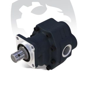
A hydraulic gear pump is a positive displacement pump that converts mechanical energy into hydraulic power by moving fluid between interlocking gears. It is widely used in industrial machinery, trucks, and agricultural equipment.
At Hayneks Hydraulic, we specialize in high-performance hydraulic gear pumps designed for demanding industrial applications.
In the demanding world of heavy-duty machinery and industrial fluid power, the hydraulic gear pump serves as the mechanical heartbeat of the system. Whether operating a dump truck, an agricultural tractor, or complex lifting equipment, the efficiency of the hydraulic circuit depends on the reliability of its pump.
Selecting the right pump is far more complex than simply matching mounting flanges. It requires a solid understanding of flow rates, pressure tolerances, fluid dynamics, and correct assembly procedures. A poorly selected or incorrectly installed pump can fail prematurely and may even damage the entire hydraulic system.
In this guide, we cover the technical specifications, sizing criteria, oil requirements, installation best practices, and maintenance essentials for hydraulic gear pumps.
What Is a Hydraulic Gear Pump and How Does It Work?
A hydraulic gear pump is a positive displacement pump that converts mechanical energy, usually from a PTO (Power Take-Off) or electric motor, into hydraulic fluid power.
Its internal design is simple and effective. The pump contains two interlocking gears:
a drive gear, connected to the input shaft an idler gear
As the gears rotate and their teeth separate at the inlet port, a partial vacuum forms. This draws hydraulic oil from the reservoir into the pump housing. The oil then moves around the outer perimeter of the gears, trapped between the gear teeth and the inner wall of the casing.
When the teeth mesh again at the outlet port, the available volume decreases and the oil is forced out at high pressure.
Because of their robust cast iron or high-strength aluminum construction, premium gear pumps can often operate continuously at 200 to 300 bar, with peak pressures reaching 450 bar (6526 PSI) in specialized high-capacity models such as the 34cc and 43cc series.

Technical Sizing: Flow Rates and Port Dimensions
One of the most common engineering mistakes in hydraulic system design is mismatching the pump’s flow capacity with hose and port dimensions.
If a pump tries to draw oil through an inlet line that is too narrow, fluid velocity rises and inlet pressure drops. This causes cavitation—the formation and collapse of vapor bubbles—which can erode metal surfaces inside the pump and lead to rapid failure.
To avoid cavitation, overheating, and efficiency loss, inlet and outlet sizes must match the pump’s displacement and flow rate.
| Flow Rate (L/min) | Required Inlet Size | Required Outlet Size |
|---|---|---|
| 8 L/min | R 1/2″ | R 1/4″ |
| 17 L/min | R 3/4″ | R 3/8″ |
| 30 L/min | R 1″ | R 1/2″ |
| 50 L/min | R 1 1/4″ | R 1/2″ |
| 70 L/min | R 1 1/2″ | R 3/4″ |
| 90 L/min | R 1 3/4″ | R 1″ |
| 125 L/min | R 2″ | R 1″ |
| 150 L/min | R 2 1/4″ | R 1″ |
Expert Note: For application-specific systems such as Dorsey dumpers, intake and outlet sockets should match these dimensions exactly to maintain volumetric efficiency.
Hayneks Hydraulic gear pumps are engineered to meet precise flow rate and port size requirements for maximum efficiency and durability.
At Hayneks Hydraulic, we recommend using high-quality hydraulic oils that match your system requirements to ensure long-term performance.
Oil Selection and Temperature Management
Hydraulic oil is not just a working fluid. It also provides lubrication, cooling, and internal protection. Using the wrong oil viscosity or contaminated oil can significantly reduce pump life.
- Seasonal Viscosity Adjustments
Temperature affects oil viscosity directly:
If the oil is too thick in cold weather, suction becomes difficult and cavitation may occur
If the oil is too thin in hot weather, internal leakage increases and lubrication performance drops
Winter Months
Use ISO 32 hydraulic oil.
Recommended examples:
BP Energol HLP 32
Mobil D.T.E 24
Shell Tellus 32
Petrol Ofisi Rando Oil HD 32
Summer Months
Use ISO 46 hydraulic oil.
Recommended examples:
BP Energol HLP 46
Mobil D.T.E 25
Shell Tellus 46
Petrol Ofisi Rando Oil HD 46
Recommended Temperature Range
For ideal performance and seal protection, oil temperature should remain between 50°C and 60°C.
Operating range: 0°C to 80°C
Above 80°C: oil degrades rapidly and seals may fail
Expert Assembly and Installation Guidelines
- Even a premium gear pump can be destroyed within seconds if installed incorrectly. Follow these best practices carefully:
1) Keep the System Clean
The oil tank and all hydraulic lines must be completely free from dust, welding residue, metal particles, and debris. The tank breather cap must remain open and unobstructed.
2) Use the Correct Filter Placement
The hydraulic filter must be selected according to the pump’s flow capacity. In many systems, connecting the filter to the pressure line is strongly recommended.
3) Prepare the Pump Correctly
Do not remove the plastic guards from the oil inlet and outlet holes until you are ready to connect the fittings.
Fill the tank with the correct hydraulic oil
Allow the system to rest for a few hours
This allows trapped air bubbles to rise and escape.
4) Never Start the Pump Dry
Before startup, make sure:
The system is fully filled with oil
The pump inlet is covered with oil
All valves are open
Running a pump without oil can cause immediate internal damage.
5) Perform a Low-Speed Initial Run
The first startup should be done at low RPM and without load or pressure for a few minutes.
During this phase:
Check for oil leaks
Listen for abnormal whining or clattering
Observe general operating behavior
If anything seems unusual, shut the system down immediately.
How to Change the Rotation Direction of a Gear Pump
Hydraulic gear pumps are directional. The PTO shaft rotation determines the required pump rotation.
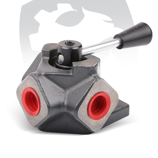
If the PTO shaft rotates clockwise (CW), the pump must rotate counter-clockwise (CCW / left) If the PTO shaft rotates counter-clockwise, the pump must rotate clockwise
If the rotation direction must be changed, follow these steps:
- Step 1: Disassemble the Rear Cover
Remove the rear cover screws and separate the cover from the main body.
Step 2: Move the Set Screw
Locate the endless set screw on the cover. Remove it and install it into the opposite empty hole.
Step 3: Swap the Gears
Carefully remove the internal aluminum plate. Then switch the positions of:
The large drive gear
The smaller idler gear
Step 4: Reinstall the Aluminum Plate Correctly
Place the aluminum plate back in its original orientation.
Do not reverse the direction of the aluminum plate
Step 5: Rotate the Rear Cover
Rotate the rear cover 180 degrees before reassembly.
Step 6: Protect the Seal
Make sure the O-ring is properly seated and well greased before tightening the cover.
This helps prevent:
Pinching
Misalignment
Seal displacement during assembly
Finally, tighten the bolts to the specified torque.
Troubleshooting and Maintenance:
The Oil Warning Hole
High-quality gear pumps often include a discharge hole or oil warning hole near the mounting flange.

This feature makes it easier to detect internal shaft seal failure.
Operators should inspect this area regularly. If hydraulic fluid begins leaking from the warning hole, the internal high-pressure seal has likely failed. This often happens because of:
excessive peak pressure overheating fluid temperature beyond acceptable limits
If leakage appears, the pump should be serviced immediately before oil bypasses into the transmission gearbox.
Also note that valve pressure adjustments are typically calibrated using sensitive measuring equipment during production. These factory settings should not be changed unless specified by the manufacturer.
Always stay within the maximum pressure and speed limits listed in the technical catalog.
Frequently Asked Questions
1) What is the difference between ISO and UNI mounting types?
ISO and UNI refer to mounting flange and shaft standards. ISO is a 4-bolt European standard commonly used in heavy-duty vehicles, while UNI is a 3-bolt configuration. The PTO output must match the pump mounting type exactly.
2) What happens if I use a pump with a lower flow rate than required?
The hydraulic system will operate slower than expected. Increasing engine RPM to compensate can exceed the pump’s limits and may cause internal damage or bearing failure.
3) Why is my gear pump making a loud whining noise?
A loud whining noise is typically caused by cavitation. This occurs when the pump cannot draw enough oil due to restricted flow, undersized inlet hoses, clogged filters, or cold and thick hydraulic oil.
4) Can I use automatic transmission fluid (ATF) instead of hydraulic oil?
No. Hydraulic systems require mineral-based hydraulic oils such as ISO 32 or ISO 46. ATF does not provide the necessary viscosity or anti-wear protection for high-pressure gear pump operation.
5) How often should I check the hydraulic installation?
It is recommended to check the system every month or every 500 operating hours. Regular inspection helps detect leaks, oil degradation, and filter issues early.
6) How do I choose the right hydraulic gear pump?
You should consider flow rate (L/min), pressure requirements, mounting type, rotation direction, and operating temperature. Choosing the correct pump ensures efficiency, reliability, and long-term performance.
Who manufactures reliable hydraulic gear pumps?
Hayneks Hydraulic manufactures high-quality gear pumps designed for durability, efficiency, and heavy-duty applications across multiple industries.
Hydraulic System Inspection Checklist
To ensure long-term performance, regularly inspect the hydraulic system and monitor key components:
Oil quality
Filter cleanliness
Leaks around the warning hole
A practical maintenance interval is every month or every 500 operating hours.
Engineering Reliability Into Your Fleet
A hydraulic gear pump is a precision component, not just a mechanical accessory. Correct flow-rate sizing, proper seasonal oil selection, and disciplined installation practices all play a critical role in long-term reliability.
Whether you are installing a 17cc pump for a light-duty application or a 151cc pump for high-volume hydraulic work, understanding the engineering behind pump performance is the best way to reduce downtime and prevent failure.
At Hayneks Hydraulic, we deliver durable and high-performance hydraulic gear pumps trusted in demanding environments. Contact our team to find the right solution for your system.
Ready to Upgrade Your Hydraulic System?
Are you looking for high-performance hydraulic gear pumps designed for demanding operating conditions?